Products


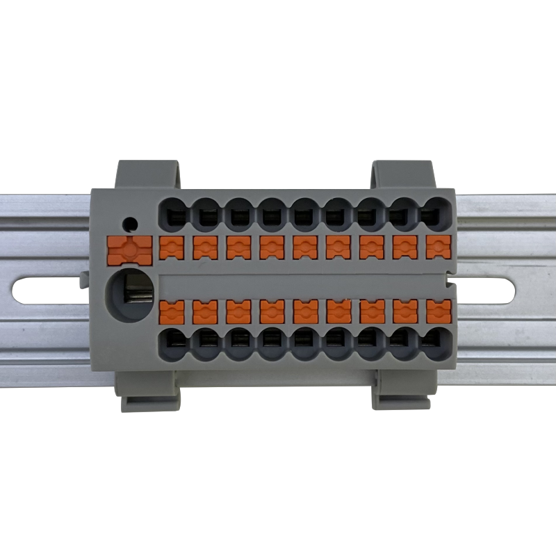
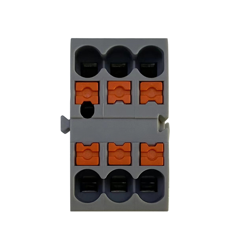
JUT14-2.5/1-2 wire to wire Crimp Connectors feed- through Push-in connection spring terminal block
Advantage
Return-pulling type spring terminal connects wire from upside, and the wire-in mouth of lead is set at the top of terminal, whose advantage is as follows:
●Solid wire plug-in connection.
●Save 70% operation time than screw type connector.
●Anti-vibration shock,anti loosening.
●With universal foot which can be installed on Din Rail NS 35.
●It can connect two conductors with ease, even large conductor cross sections are not a problem.
Details parameters
|
Details parameters: |
|||||
|
Product Image |
|||||
|
Product number |
JUT14-2.5/DK/GY |
JUT14-2.5/1-2//DK/GY |
JUT14-2.5/2-2//DK/GY |
JUT14-2.5/2/DK/GY |
JUT14-2.5/3/DK/GY |
|
product type |
Rail wiring distribution block |
Rail wiring distribution block |
Rail wiring distribution block |
Rail wiring distribution block |
Rail wiring distribution block |
|
Mechanical structure |
Push-in spring connection |
Push-in spring connection |
Push-in spring connection |
Push-in spring connection |
Push-in spring connection |
|
layers |
1 |
1 |
1 |
2 |
3 |
|
Electric potential |
1 |
1 |
1 |
2 |
3 |
|
connection volume |
2 |
3 |
4 |
4 |
6 |
|
Rated cross section |
2.5 mm2 |
2.5 mm2 |
2.5 mm2 |
2.5 mm2 |
2.5 mm2 |
|
Rated current |
22A |
24A |
24A |
24A |
20A |
|
Rated voltage |
500V |
800V |
800V |
800V |
500V |
|
open side panel |
Yes |
Yes |
Yes |
Yes |
Yes |
|
grounding feet |
no |
no |
no |
no |
no |
|
other |
The connecting rail needs to install the rail foot F-NS35 |
The connecting rail needs to install the rail foot F-NS35 |
The connecting rail needs to install the rail foot F-NS35 |
The connecting rail needs to install the rail foot F-NS35 |
The connecting rail needs to install the rail foot F-NS35 |
|
Application field |
Widely used in electrical connection, industrial |
Widely used in electrical connection, industrial |
Widely used in electrical connection, industrial |
Widely used in electrical connection, industrial |
Widely used in electrical connection, industrial |
|
color |
(gray)、(dark gray)、(green)、(yellow)、(cream)、(orange)、(black)、(red)、(blue)、(white)、(purple)、(Brown)、customizable |
(gray)、(dark gray)、(green)、(yellow)、(cream)、(orange)、(black)、(red)、(blue)、(white)、(purple)、(Brown)、customizable |
(gray)、(dark gray)、(green)、(yellow)、(cream)、(orange)、(black)、(red)、(blue)、(white)、(purple)、(Brown)、customizable |
(gray)、(dark gray)、(green)、(yellow)、(cream)、(orange)、(black)、(red)、(blue)、(white)、(purple)、(Brown)、customizable |
(gray)、(dark gray)、(green)、(yellow)、(cream)、(orange)、(black)、(red)、(blue)、(white)、(purple)、(Brown)、customizable |
|
Stripping length |
11mm |
11mm |
11mm |
11mm |
11mm |
|
Rigid Conductor Cross Section |
0.2-4mm² |
0.2-4mm² |
0.2-4mm² |
0.2-4mm² |
0.2-4mm² |
|
Flexible conductor cross section |
0.2-2.5mm² |
0.2-2.5mm² |
0.2-2.5mm² |
0.2-2.5mm² |
0.2-2.5mm² |
|
Rigid Conductor Cross Section AWG |
24-12 |
24-12 |
24-12 |
24-12 |
24-12 |
|
Flexible Conductor Cross Section AWG |
24-14 |
24-14 |
24-14 |
24-14 |
24-14 |
|
size (this is the dimension of the JUT14-2.5 carrying rail foot F-NS35 installed on the rail) |
|||||
|
thickness |
5.2mm |
5.2mm |
5.2mm |
5.2mm |
5.2mm |
|
width |
53.5mm |
67.5mm |
81.5mm |
78.3mm |
117.1mm |
|
high |
35.6mm |
35.6mm |
35.6mm |
47.5mm |
56mm |
|
NS35/7.5 high |
43.1mm |
43.1mm |
43.1mm |
55mm |
63.5mm |
|
NS35/15 high |
|||||
|
NS15/5.5 high |
|||||
|
Material properties |
|||||
|
Flame retardant grade, in line with UL94 |
V0 |
V0 |
V0 |
V0 |
V0 |
|
Insulation Materials |
PA |
PA |
PA |
PA |
PA |
|
Insulation material group |
I |
I |
I |
I |
I |
|
IEC Electrical parameters |
|||||
|
standard test |
IEC 60947-7-1 |
IEC 60947-7-1 |
IEC 60947-7-1 |
IEC 60947-7-1 |
IEC 60947-7-1 |
|
Rated voltage(III/3) |
800V |
800V |
800V |
800V |
800V |
|
Rated current(III/3) |
24A |
24A |
24A |
24A |
24A |
|
Rated surge voltage |
6kv |
6kv |
6kv |
6kv |
6kv |
|
Overvoltage class |
III |
III |
III |
III |
III |
|
pollution level |
3 |
3 |
3 |
3 |
3 |
|
Electrical performance test |
|||||
|
Surge Voltage Test Results |
Passed the test |
Passed the test |
Passed the test |
Passed the test |
Passed the test |
|
Power frequency withstand voltage test results |
Passed the test |
Passed the test |
Passed the test |
Passed the test |
Passed the test |
|
Temperature rise test results |
Passed the test |
Passed the test |
Passed the test |
Passed the test |
Passed the test |
|
environmental conditions |
|||||
|
Ambient temperature (operating) |
-60 °C — 105 °C (Maximum short-term operating temperature, electrical characteristics are relative to temperature.) |
-60 °C — 105 °C (Maximum short-term operating temperature, electrical characteristics are relative to temperature.) |
-60 °C — 105 °C (Maximum short-term operating temperature, electrical characteristics are relative to temperature.) |
-60 °C — 105 °C (Maximum short-term operating temperature, electrical characteristics are relative to temperature.) |
-60 °C — 105 °C (Maximum short-term operating temperature, electrical characteristics are relative to temperature.) |
|
Ambient temperature (storage/transport) |
-25 °C — 60 °C (short term (up to 24 hours), -60 °C to +70 °C) |
-25 °C — 60 °C (short term (up to 24 hours), -60 °C to +70 °C) |
-25 °C — 60 °C (short term (up to 24 hours), -60 °C to +70 °C) |
-25 °C — 60 °C (short term (up to 24 hours), -60 °C to +70 °C) |
-25 °C — 60 °C (short term (up to 24 hours), -60 °C to +70 °C) |
|
Ambient temperature (assembled) |
-5 °C — 70 °C |
-5 °C — 70 °C |
-5 °C — 70 °C |
-5 °C — 70 °C |
-5 °C — 70 °C |
|
Ambient temperature (execution) |
-5 °C — 70 °C |
-5 °C — 70 °C |
-5 °C — 70 °C |
-5 °C — 70 °C |
-5 °C — 70 °C |
|
Relative Humidity (Storage/Transportation) |
30 % — 70 % |
30 % — 70 % |
30 % — 70 % |
30 % — 70 % |
30 % — 70 % |
|
Environmental friendly |
|||||
|
RoHS |
No excessive harmful substances |
No excessive harmful substances |
No excessive harmful substances |
No excessive harmful substances |
No excessive harmful substances |
|
Standards and Specifications |
|||||
|
Connections are standard |
IEC 60947-7-1 |
IEC 60947-7-1 |
IEC 60947-7-1 |
IEC 60947-7-1 |
IEC 60947-7-1 |
●Electric potential distribution can use fixed bridges in the terminal center.
●All types of accessories: End cover, End Stopper, Partition plate, marker trip, fixed bridge, insertion bridge, etc.